基于绕组函数的内置永磁电机电枢反应磁场特性研究毕业论文
2020-07-11 18:01:19
摘 要
由于永磁体(IPM)电机的转子中嵌入了磁体,因此电枢反应磁场的分布与表面永磁电机(SPM)类型的分布不同。已经使用了各种方法用于磁场解,包括基于缠绕函数和拉普拉斯 - 泊松方程的分析方法。但是,在IPM电机中,对于使用拉普拉斯 - 泊松方程,边界条件太复杂。此外,文献中提出的等效气隙反函数不适用于IPM电机。针对IPM电机提出了一种新的电枢反应磁场模型,该模型考虑了嵌入式磁体在转子中的作用,本文称其为极帽效应。所提出的模型是从绕组函数理论推导出来的,并且转子磁动力(MMF)函数被用来模拟所谓的极点效应。 所提出的模型用于预测不同类型的定子MMF下的电枢反应场,例如激励电流的不同取向以及各种MMF波长。计算结果通过有限元分析(FEA)验证,并显示出超越传统方法的显着优势。 本文提出的新模型对于以准确和时间有效的方式评估各种IPM电机性能非常有用,如电感,定子铁心损耗和磁涡流损耗。
近几十年来,内部永磁(IPM)电机由于其高效率,宽转速范围以及对于给定转矩的小尺寸和重量而被广泛用于高性能应用。 准确评估电枢反应磁场是非常重要的,因为它为获得IPM电机的参数和性能指标(例如电感,铁损和转矩波动)奠定了基础。 已经提出了不同的方法来实现这一点。 这些方法大致分为两类:基于绕组函数的分析方法和拉普拉斯 - 泊松方程。
由于磁体嵌入IPM电机的转子中,边界条件过于复杂,无法基于拉普拉斯 - 泊松方程得到电枢反应场分布。因此,这种方法只适用于获得磁场分布的表面永磁电机(SPM)和表面嵌入永磁体(PM)马达。 根据现场分布,表现已经获得了诸如SPM中的涡流损耗等指标。
因此,当谈到IPM电机中的电枢反应磁场分析时,基于绕组功能的分析方法是一个有吸引力的候选方案。 在这种方法中,采用绕组函数来描述响应于瞬时电流激励的定子磁动力(MMF)的空间分布。 气隙反函数被定义为表示在定子架中看到的磁阻变化。 气隙磁场密度分布可以由绕组函数和气隙反函数得出。
这种方法在1965年首次引入,并用于分析感应电动机。 自1992年以来,该理论已被应用于研究感应电动机故障分析的性能,当气隙反函数是固定幅度的直线时。 到目前为止,绕组函数法已被扩展到分析凸极同步和磁阻同步电机,表面永磁电机和IPM电机。
在文献中,提出了一种改进的气隙反函数用于表面插入永磁电机的电枢反应场评估。与原始气隙反函数不同,修正函数的幅值不是恒定的磁铁存在。这项工作提供了一个简单的方法来计算修改后的等效气隙反函数:安装磁体的隔板的气隙高度被视为实际气隙高度和磁体高度的总和,剩余的分区仅被视为实际的气隙。
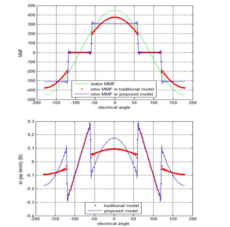
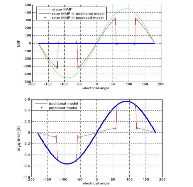
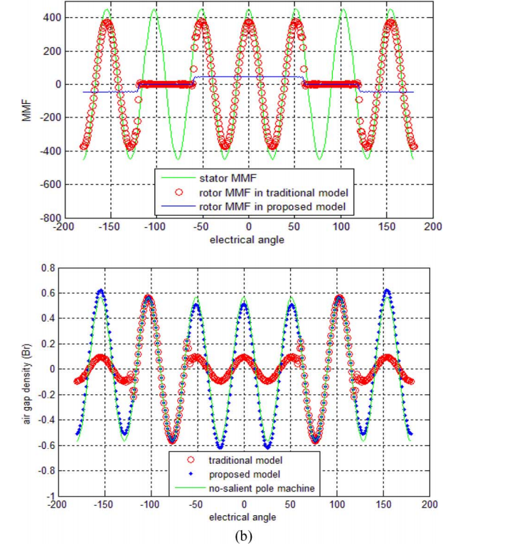
但是,在IPM电机中,情况不同,使得文献中的方法不能很好地工作。磁体上方的几乎无限的磁极帽使得磁体的上表面成为等电位区域,这在本文中被称为极帽效应。 因此,在IPM电机中,等效气隙反函数不能表示为同步电机或表面嵌入式永磁电机的形式。
使用转子MMF函数代替修正的气隙反函数来模拟极点效应。 然而,转子MMF被表示为模糊表达,并且利用有限元分析(FEA)和磁等效电路(MEC)来获得用于转矩脉动和涡流损耗优化的转子MMF功能。
本文提出了一种基于绕组函数和转子线性矩阵不等式(MMF)预测IPM电机电枢反应磁场的分析方法。 为了计算转子MMF函数,建立转子MMF和定子MMF之间的关系。
所提出的模型用于预测不同类型的定子MMF下的电枢反应场,例如激励电流的不同取向以及各种MMF波长。 计算结果经有限元分析验证,与传统方法相比具有显着的优势。 本文提出的新模型对于以准确和时间有效的方式评估各种IPM电机性能非常有用,如电感,定子铁心损耗和磁涡流损耗。
关键词:电枢反应磁场,内置永磁(IPM)电机,极帽效应,绕组函数的分析法。
Armature-Reaction Magnetic Field Analysis for Interior Permanent Magnet Motor Based on Winding Function Theory
Abstract
Since magnets are embedded in the rotor of a permanent magnet (IPM) motor, the distribution of the armature reaction magnetic field is different from that of the surface permanent magnet motor (SPM) type. Various methods have been used for magnetic field solutions, including analytical methods based on the winding function and the Laplace-Poisson equation. However, in the IPM motor, the boundary conditions are too complicated for using the Laplace-Poisson equation. In addition, the equivalent air gap inverse function proposed in the literature is not applicable to IPM motors. A new armature reaction magnetic field model is proposed for IPM motors. This model takes into account the role of the embedded magnet in the rotor, which is referred to as a pole cap effect in this paper. The proposed model is derived from the winding function theory, and the rotor magnetic force (MMF) function is used to model the so-called pole effect. The proposed model is used to predict armature reaction fields under different types of stator MMF, such as different orientations of the excitation current and various MMF wavelengths. The calculations were validated by Finite Element Analysis (FEA) and showed significant advantages over traditional methods. The new model presented in this paper is useful for evaluating the performance of various IPM motors in an accurate and time-efficient manner, such as inductance, stator core losses, and eddy current losses.
In recent decades, internal permanent magnet (IPM) motors have been widely used for high performance applications due to their high efficiency, wide speed range, and small size and weight for a given torque. Accurate evaluation of the armature reaction magnetic field is very important because it lays the foundation for obtaining IPM motor parameters and performance indicators such as inductance, core loss and torque ripple. Different methods have been proposed to achieve this. These methods are roughly divided into two categories: analysis methods based on winding functions and Laplace-Poisson equations .
Because the magnet is embedded in the rotor of the IPM motor, the boundary conditions are too complex and the armature reaction field distribution cannot be obtained based on the Laplace-Poisson equation. Therefore, this method is only suitable for obtaining a magnetic field distribution of a surface permanent magnet motor (SPM) and a surface-embedded permanent magnet (PM) motor . According to the site distribution, performance has been obtained such as eddy current loss in SPM and other indicators .
Therefore, when it comes to analysis of the armature reaction magnetic field in an IPM motor, an analysis method based on the winding function is an attractive candidate. In this method, a winding function is used to describe the spatial distribution of stator magnetic force (MMF) in response to instantaneous current excitation. The air gap inversion function is defined as representing the change in magnetoresistance seen in the stator frame . The air gap magnetic field density distribution can be derived from the winding function and the inverse air gap function.
This method was first introduced in 1965 and used to analyze induction motors . Since 1992, this theory has been applied to the study of the performance of induction motor fault analysis when the air gap inversion function is a fixed-amplitude straight line. So far, the winding function method has been extended to analyze salient-pole synchronous and reluctance synchronous motors, surface permanent magnet motors and IPM motors .
an improved air gap inverse function is proposed for the evaluation of the armature reaction field with surface-inserted permanent magnet motors. Unlike the original inverse air gap function, the magnitude of the correction function in is not a constant magnet. This work provides a simple method to calculate the modified inverse air gap equivalent function: the height of the air gap of the spacer on which the magnet is installed is considered as the sum of the actual air gap height and the magnet height, and the remaining partitions are considered only Actual air gap.
However, in the case of IPM motors, the situation is different and the methods in the literature do not work well. Nearly infinite pole caps above the magnets cause the upper surface of the magnets to be in the equipotential region, which is referred to herein as the pole cap effect. Therefore, in the IPM motor, the equivalent air gap inverse function cannot be expressed as the form of a synchronous motor or a surface-embedded permanent magnet motor .
the pole effect is simulated using the rotor MMF function instead of the modified air gap inverse function. However, the rotor MMF is expressed as a fuzzy expression, and a finite element analysis (FEA) and a magnetic equivalent circuit (MEC) are used to obtain the rotor MMF function optimized for torque ripple and eddy current loss.
相关图片展示:
