汽车盘式制动器设计毕业论文
2021-03-13 22:23:39
目录
Chapter 1 Introduction 2
1.1 Brake system overview 2
1.1.1 Automotive brake operation 2
1.1.2 Brake System Components 4
1.1.3 Types of Braking System 5
1.1.4 Type of Dual Split System 6
1.2 Introduction and Features of Brake 7
1.2.1 Overview of the Brake 7
1.2.2 Types of disc brakes 8
1.2.3 Application of dis brake 11
1.2.4 The request of a braking system design 12
Chapter 2 Design and Analysis of Brakes’ Structure 16
2.1 Analysis and Determination of Brakes 16
2.2 The Selection and Analysis of the Driving Mechanism 17
2.2.1 The Simple Driving Mechanism 18
2.2.2 The Power Driving Mechanism 18
2.2.3 Power-assisted Mechanism 19
Chapter 3 The Design of Brake 22
3.1 Reference model and the data used in design. 22
3.2 The calculation and Selection of Braking system 22
3.2.1 Synchronous adhesion coefficient 22
3.2.2 Calculation of Normal Force 24
3.2.3 The calculation of distribution coefficient. 27
3.2.4 Braking strength and adhesion coefficient utilization. 28
3.2.5 Calculation of adhesion force 29
3.2.6 Calculation of braking force and the braking torque. 30
3.2.7 Brake factor and the brake sensitivities 30
3.3 The Design of the Brake’s Structure 32
3.3.1 The diameter of brake disc D 32
3.3.2 The thickness of brake disc h 32
3.3.3 The parameters of brake friction pad 33
3.4 Calculation of parking braking system 35
Chapter 4 Design of Disc Brake System Components 36
4.1 Brake disc 36
4. 2 Disc Brake Caliper 36
4.3 Material of Friction 37
4.4 Brake Pads 39
4.5 Braking Clearance 40
4.6 Master Cylinder 40
4.7 Wheel Cylinder Construction and Operation 41
Conclusion 53
Acknowledgement 54
Chapter 1 Introduction
1.1 Brake system overview
The basic functions of a brake system are to decelerate a vehicle including stopping, to keep its speed stable during downhill operation, and to hold the vehicle stationary after the vehicle come to a complete stop.
All the force acting on vehicle can be a braking as soon as its direction against the driving direction, including the rolling resistance, air resistance, grade resistance and so on. However, the forces above are random and out of control. The safe operation of a cars requires continuous adjusting of its speed to changing road condition and traffic situation, so there must be a certain extent constraint brake on car while driving, which means we should provide a braking force by our vehicle. And the brake forces are applied by a brake system.
1.1.1 Automotive brake operation
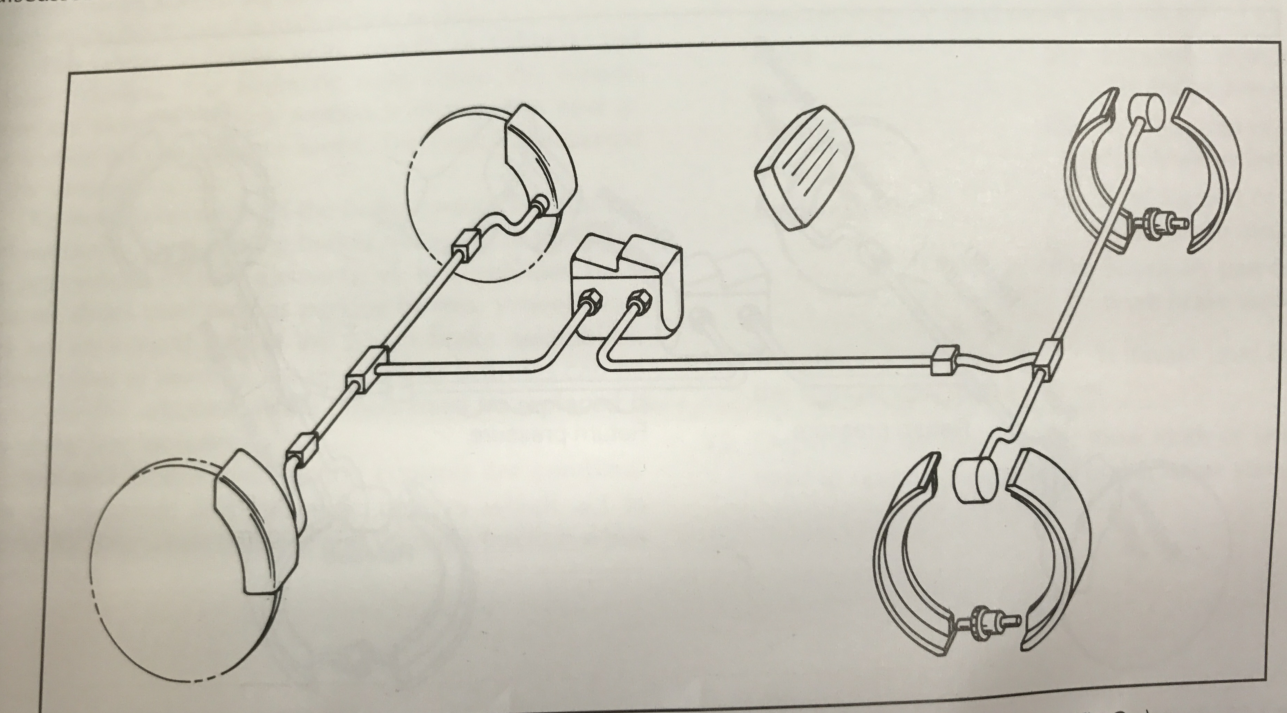
In the Figure 1-1, the brake system is inactive. When the pedal is not being depressed, and there is not force applied to the master cylinder pushrod. As there are not hydraulic pressure created within the master cylinder, there is not force delivered to the lines and horse. Without pressure, the caliper pistons and wheel cylinder can’t apply the friction materials. Spring and seal pressure keeps the brake pads and shoes in the released position. The brake system is not operating.

(Figure 1-1 A simple brake system in the inactive mode)
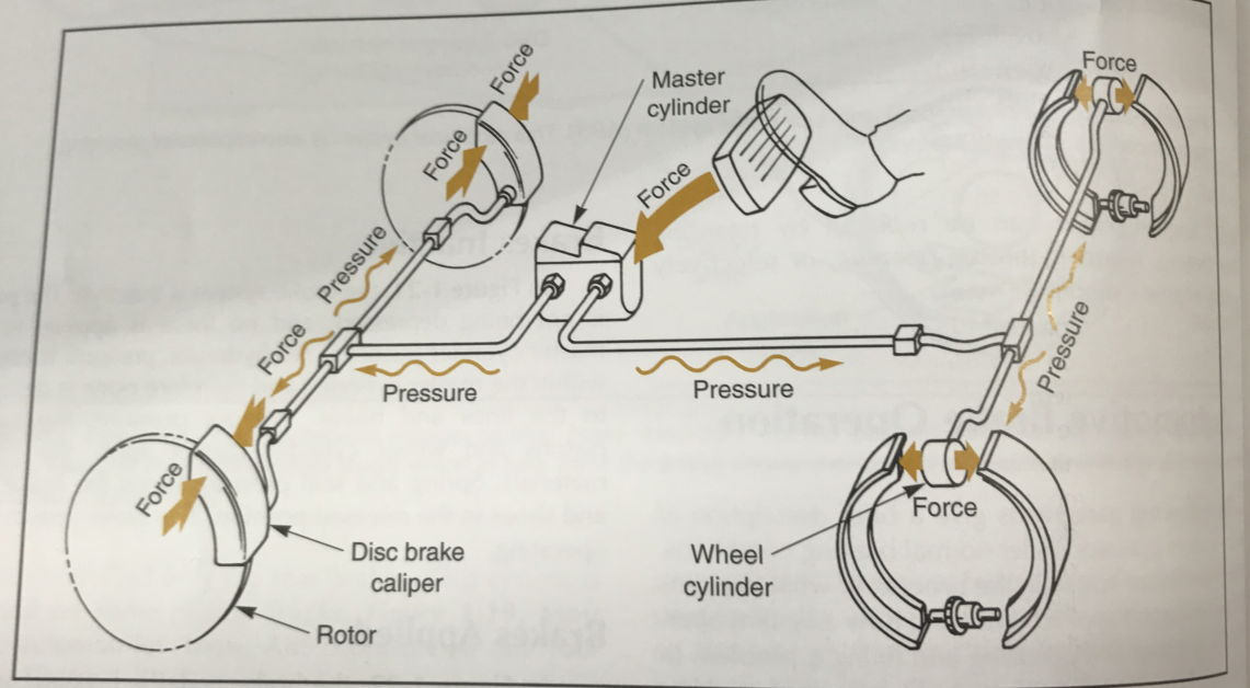
In figure 1-2, when driver is pushing the brake pedal, the pushrod of master cylinder is forced inward, which will create hydraulic pressure in the master cylinder. As pressure is transmitted into the caliper pistons and wheel cylinders by the brake line. In our vehicles, the front brake and rear brake are all controlled by the valves. Pressures make the caliper piston move, causing the brake pads against the rotor, leading to the outward of wheel cylinder pistons, moving the brake shoes into contact with brake drum. The vehicle will slow, because of the contact of stationary and rotating friction members.
The heat generated by the friction is released into the surrounding air.

(Figure 1-2 Simple brake system shown in the applied mode)
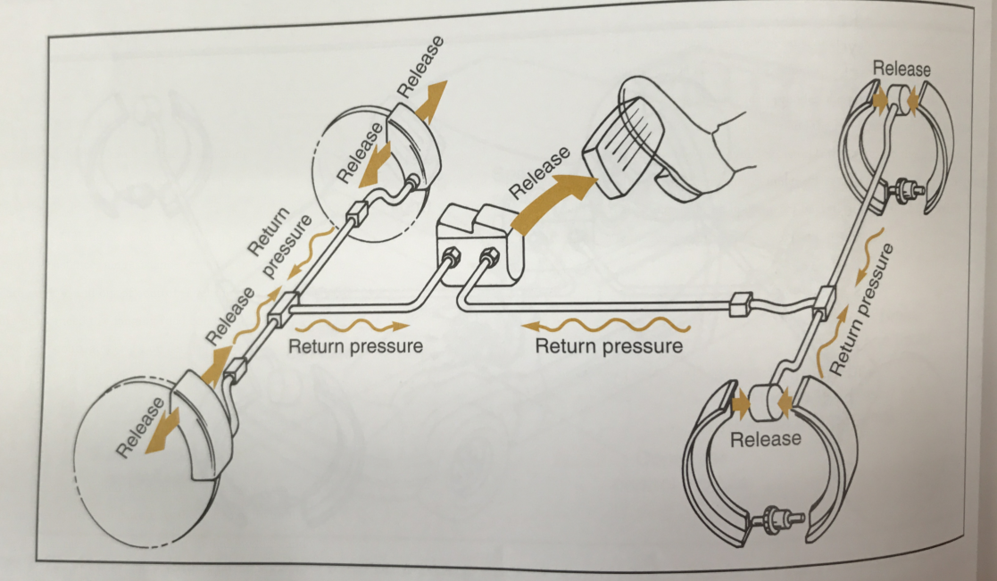
In Figure1-3, after releasing the brake pedal, hydraulic pressure drops off, the caliper piston seals pull the piston back into the cylinder. Which releases the brake pads and the rotor can become freely. In the wheel cylinder, the pistons are pushed back into the cylinders by the brake shoes return springs and the drum can turn with no resistance. When both the caliper and wheel cylinder pistons move back to the cylinders, the fluid is displaced and returns to the master cylinders. The fluid returning to master cylinder helps an internal spring push the brake pedal back to its released position. Any extra fluid flows in to the reservoir.

(Figure 1-3 Simple brake system in the released mode)
1.1.2 Brake System Components
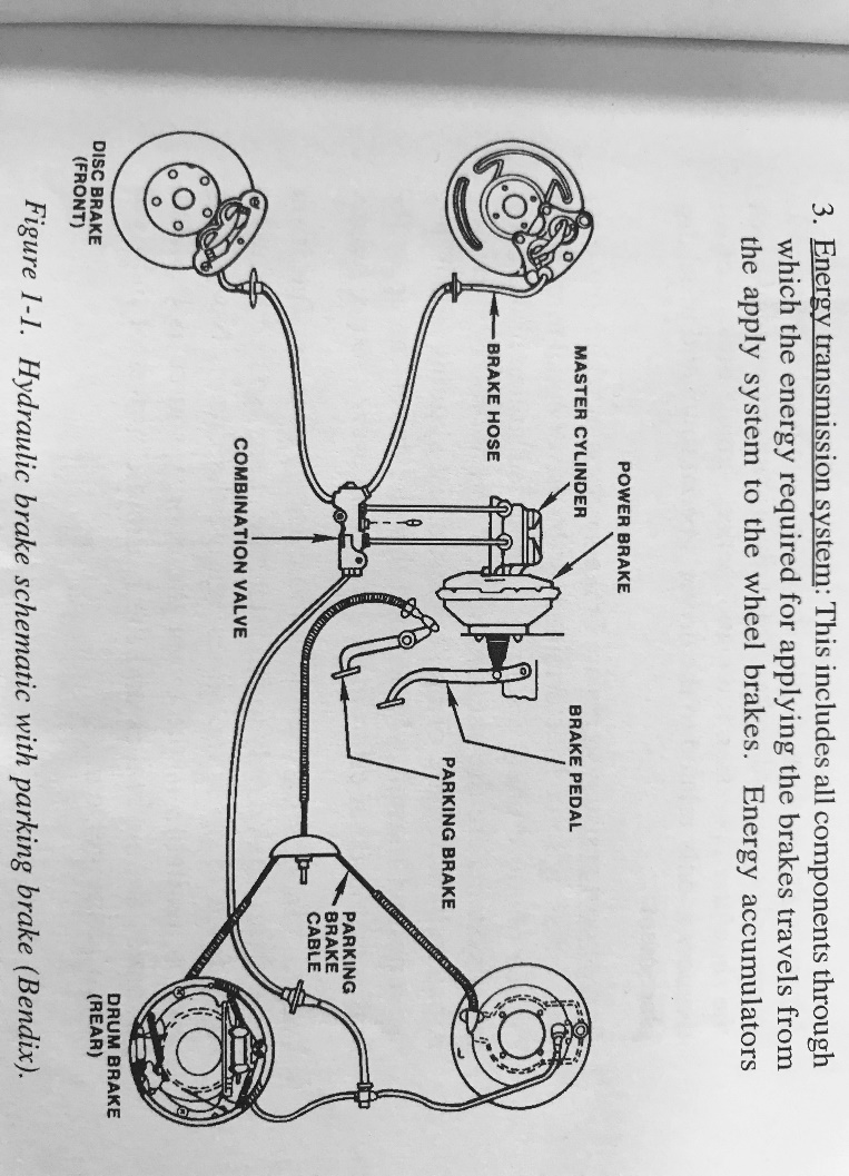
As Figure 1-4 shown, it is a typical hydraulic brake system, and all brake systems can be divided into 4 parts.
- Energy source: This includes the components of a brake system that produce, store, and available the energy required for braking. The energy source subsystem ends where driver-controlled modulation of the energy supply begins.
- Apply system: All the components that are used to modulate the level of braking belong to this part. The apply subsystem ends where the energy required for applying the brake enters the energy transmission system.
- Energy transmission system: This includes all parts through which the energy required for applying the brakes travels from the apply system to the wheel brakes. Energy accumulators located in the system are part of energy transmission system. This system ends at the component where retarding brake torque is developed. For a hydraulic brake system, it ends where the wheel cylinder piston contacts the brake shoe. Brake tubes required for carrying hydraulic or air medium tubes commonly are called brake lines, whereas flexible tubes are called brake hoses.
- Wheel or foundation brakes: These are the parts where the brake force are produced which oppose the existing or intended vehicle motion.

(Figure 1-4 Hydraulic brake schematic with parking brake)
1.1.3 Types of Braking System
- According to the functions
- Service braking system: Used for normal braking, reduce the speeds of cars while driving.
- Parking braking system: Used when parking, to hold the vehicle stationary after parking.
- Emergency braking system: in the case of failure of the service braking system, make sure the vehicle can still slow down and stop.
- Additional retarding braking system: assist the service braking system while driving.
- According to the energy sources
(1)Muscular energy braking system: The brake system which uses the collective of the driver’s manmade power as the only brake energy.


