弹性结构的低频振动能量收集系统毕业论文
2021-12-10 17:43:19
论文总字数:23579字
摘 要
近年来,便携式电子设备和可穿戴电子的发展达到了前所未有的高度,这些微型设备具有超低的功耗和更小的体积,而在能量收集领域,压电材料最为常用。但是传统的压电陶瓷由于其本身柔韧性较差,很难适用于该领域中,同时,在人类生活和生产的环境中存在着各种低频机械振动源可被利用。因此,人们急需找到一种能在高弹性、低振动频率下工作的材料。压电纤维复合材料以压电陶瓷纤维和聚合物基底复合而成,同时具有压电性能和柔韧性,可以满足在低频振动下能量收集的要求,能够满足可穿戴产品的供能需求。
本论文主要研究工作和结论如下:
(1)以PZT-5A为原材料制备压电陶瓷纤维,并对其进行了结构表征,测试了其主要的电学参数。使用切割填充法制备MFC,详细介绍了MFC的制备方法,测量了MFC的P-E曲线,证明了所制备的MFC具有良好的铁电性能。
(2)使用有限元分析软件COMSOL建立了压电悬臂梁的简单模型,并对其进行仿真模拟,研究了低频条件下振动频率对压电悬臂梁的输出电压和电流的影响,并根据仿真结果指导了实验。
(3)搭建了压电悬臂梁系统,通过改变悬臂梁的基板材料,测量了悬臂梁系统在不同频率的振动下的输出电压,得到了不同基板的压电悬臂梁的谐振频率。结果表明:环氧树脂板做基板时谐振频率为17Hz,输出电压为3.3V;铝板做基板时谐振频率为18Hz,输出电压为2.6V;碳纤维板做基板时谐振频率为15Hz,输出电压为1.3V。同时,测量了其能量收集的最高功率,环氧树脂板做基板时最佳功率为13.5μW,铝板做基板时最佳功率为8.3μW,碳纤维板做基板时最佳功率为2.6μW。
(4)将实测值与仿真值进行对比后发现:环氧树脂板做基板时实测谐振频率偏移了2Hz,铝板做基板时实测谐振频率偏移了3Hz,碳纤维板做基板时实测谐振频率偏移了2Hz,最大偏差不超过16%。有限元仿真较好的指导了实验的开展,验证了MFC适合在弹性结构的低频振动下作为能量收集器件使用。
关键词:压电陶瓷, MFC,压电悬臂梁,能量收集
Abstract
In recent years, the development of portable electronic devices and wearable electronics had reached unprecedented heights. These miniature devices have lower power and smaller size. In the field of energy harvesting, piezoelectric materials are the most commonly used. However, due to their poor flexibility, traditional piezoelectric ceramics are difficult to apply to this field. At the same time, there are various low-frequency mechanical vibration sources that can be used in the environment of human life and production. Therefore, people urgently need to find a material that can work under high elasticity and low vibration frequency. Piezoelectric fiber composite materials are composited with piezoelectric ceramic fibers and polymer substrates. They also have piezoelectric properties and flexibility, which can meet the requirements for energy collection under low frequency vibration, and it can meet the energy supply requirements of wearable products.
The main research work and conclusions are as follows:
1. PZT-5A was used as the raw material to prepare the piezoelectric ceramic fiber, and the structure was characterized, and its main electrical parameters were tested. MFCs were prepared with the cutting and filling method. The preparation method of MFC was introduced in detail. The P-E curve of MFC was measured, which proved that the prepared MFC had good ferroelectric performance.
2. A simple model of the piezoelectric cantilever was established by using the finite element analysis software COMSOL, and the simulation was performed to research the influence of the vibration frequency on the output voltage and current of the piezoelectric cantilever under low-frequency conditions,and the experiments were guided based on simulation results.
3. A piezoelectric cantilever system was built. By changing the substrate material of the cantilever beam, the output voltage of the cantilever system under different frequencies of vibration was measured, and the resonance frequencies of the piezoelectric cantilever beams with different substrates were obtained. The results showed that the resonance frequency was 17Hz and the output voltage was 3.3V when the epoxy resin board was used as the substrate; the resonance frequency was 18Hz and the output voltage was 2.6V when the aluminum board was used as the substrate; the resonance frequency was 15Hz and the output voltage was 1.3V when the carbon fiber board was used as the substrate. At the same time, the highest power for energy collection was measured. The optimal power when the epoxy board was used as the substrate was 13.5 μW, the optimal power when the aluminum board was used as the substrate, and the optimal power when the carbon fiber board was used as the substrate was 2.6 μW.
4. After comparing the measured values with the simulated values, it was found that the measured resonant frequency was shifted by 2Hz when the epoxy board was used as the substrate, the measured resonant frequency was shifted by 3Hz when the aluminum board was used as the substrate, and the measured resonant frequency was shifted by 2Hz when the carbon fiber board was used as the substrate , The maximum deviation didn’t exceed 16%. Finite element simulation had guided the development of the experiment well, and verified that MFC was suitable for use as an energy harvesting device under the low frequency vibration of elastic structures.
Key Words:PZT ceramic, piezoelectric fiber composite, MFC, piezoelectric cantilever
目 录
摘要 i
Abstract ii
1.绪论 1
1.1.引言 1
1.2.国内外发展现状 1
1.2.1. 压电材料 1
1.2.2. 压电纤维复合材料 1
1.2.3. 压电能量收集的发展现状 2
1.3.论文研究意义及内容 3
2.压电纤维复合材料的制备及表征 5
2.1.压电陶瓷 5
2.1.1. PZT压电陶瓷的制备 5
2.1.2. PZT压电陶瓷的表征 5
2.2.压电纤维复合材料(MFC) 7
2.2.1. 压电纤维复合材料(MFC)的制备 7
2.2.2. 压电纤维复合材料(MFC)的表征 9
2.3.本章小结 10
3.压电悬臂梁的有限元仿真分析 11
3.1.有限元分析简介 11
3.2.建立模型 11
3.3.分析结果 12
3.3.1. 电学分析 12
3.3.2. 力学分析 13
3.4.本章小结 13
4.MFC悬臂梁的搭建与测试 15
4.1.实验平台的设计与搭建 15
4.2.实验数据分析 15
4.3.实验数据与模拟实验数据对比 16
4.4.本章小结 17
5.结论与展望 18
5.1.结论 18
5.2.展望 18
参考文献 20
致谢 22
- 绪论
- 引言
近年来,便携式电子设备和可穿戴电子的发展达到了前所未有的高度,这些微型设备具有超低的功耗和更小的体积[1-2],然而传统的化学电池具有体积大、柔性差、寿命短和存在环境污染等诸多弊端[3]。与此同时,在人类生活和生产的周围环境中存在着各种低频机械振动源可被利用[4]。因此,寻找一种高弹性、低频率、性能稳定的材料,并制备成轻质的能量收集系统成为亟需解决的问题。
在能量收集系统中,目前较为常用的是压电陶瓷材料,但是,压电陶瓷硬度高、不易变形、频率较高,在实际应用中尤其是在曲面、轻质的结构中,需要一种轻质、高弹、低频的压电复合材料来实现能量收集。
- 国内外发展现状
- 压电材料
- 国内外发展现状
自1880年P. Curie和J.Curie发现压电效应以来,压电材料得到了广泛的研究和应用。作为应用最广泛的压电材料之一,PZT (PbZrO3-PbTiO3,PZT)基压电材料仍然是应用最广泛的压电材料。PZT陶瓷具有良好的介电性能和压电性能,改性后的PZT陶瓷的d33压电系数可达779pC/N,居里温度范围可达300−400℃[5],这使PZT的反应温度更高,更接近居里温度,具有良好的热稳定性。此外,还利用各种掺杂剂制备了一系列具有部分物理性质差异的压电陶瓷,拓宽了PZT在某些特定领域的应用[6]。与此同时,适用于高温作业的压电陶瓷的需求日益增加,由于铅及其化合物在PZT高温烧结过程中易产生挥发性物质,因此近年来环保型无铅材料得到了较大的发展。学者们无铅压电陶瓷材料进行了积极的探索,包括钙钛矿结构、钨青铜结构和铋层状结构[7]。尽管取得了很大的进展,但仍然无法达到PZT陶瓷的高压电系数和热稳定性。此外,无铅压电陶瓷在不同应力、温度、频率等条件下的加工工艺、性能和应用都无法与PZT相比[8]。因此,本文使用PZT压电陶瓷作为功能相。
- 压电纤维复合材料
压电纤维复合材料是由压电陶瓷纤维和聚合物基底连结在一起,并用叉指电极封装而成的一种复合材料[9,10]。压电纤维复合材料兼具压电陶瓷的压电性能和聚合物基底的优良柔韧性,而且单向性能突出,压电纤维尺寸分布便于控制,可加工性能强,能满足不同领域对压电材料的应用需求[11],例如驱动[12]、能量收集[13]、主动/被动抑振[14]等,是当前压电复合材料研究的热点。为了克服传统压电陶瓷材料在应用上的各种不足,美国麻省理工学院的Bent等人[9]开发出了第一代压电陶瓷纤维复合材料(Active Fiber Composite,简称AFC)。AFC是由截面为圆柱形的压电纤维、环氧树脂相互填充,再用叉指电极进行封装而成,其既保留了压电陶瓷材料的压电特性,又克服了压电陶瓷材料的易碎和柔韧性差等不足。AFC 使用的电极是两个相同结构设计的叉指电极,这种电极可以使极化电场与纤维长度方向一致,增加复合材料的机电耦合系数,让长度方向的极化和响应最大化。因此其在驱动和传感领域得到了广泛关注和研究,在应用上也取得了巨大成功。但是其压电纤维的圆柱形设计导致压电陶瓷纤维与叉指电极的匹配性较差,由于圆形结构一般只在相切处与叉指电极的叉指接触,在极化过程中电压很难完全施加到压电陶瓷纤维上,并且在器件使用时,电荷从陶瓷转移到电极也会变难,除此之外,圆形截面的压电陶瓷纤维制备工艺较复杂,成本也较高。因此,美国国家航空和宇宙航行局—兰利研究中心的研究者开发出了新一代的压电纤维复合材料(Macro Fiber Composite,简称MFC) [15],其采用矩形截面压电纤维陶瓷,简化了加工过程,同时也提高了材料本身的应变性能。MFC一方面具有较好的压电性能,能实现低频下的能量收集;另一方面具有较好的柔韧性和较高的弹性模量,由其制备的能量收集系统是一种环境友好、轻质、低频、高弹性和无电磁干扰的振动能转换装置,能够满足可穿戴产品的供能需求[16]。
- 压电能量收集的发展现状
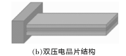
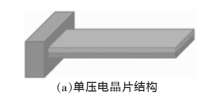 近年来,压电能量采集中最常用的是悬臂梁结构。图1.1描述了一个悬臂式压电能量收集示意图[17]。图1a展示了“单压电晶片”结构,即将一层薄的压电陶瓷内置到悬臂中,与非压电层(通常是产生电荷的金属导体)结合,其中一端固定以使结构弯曲。图1b展示了“双压电晶片”结构,悬臂通过将压电陶瓷的两个薄层接合到同一金属层上来增加单元的功率输出。相对于单压电悬臂梁,双压电悬臂梁的性能更好,具有更高的功率密度。制作的实验样机的测试结果表明,在 2.5m/s2的加速度和 120Hz 的外加振动频率下,样机的功率密度可达 70μW/cm3[18,19]。双压电悬臂梁由于其使能量收集器的能量输出加倍而体积基本不变的优势在压电能量收集研究中较为常用[20]。
图1.1 悬臂式压电能量收集器示意图
请支付后下载全文,论文总字数:23579字
相关图片展示:
