5.4起重机运动控制外文翻译资料
2023-02-24 11:25:46
5.4 Crane Motion Controls
5-4.1 Control System‑General
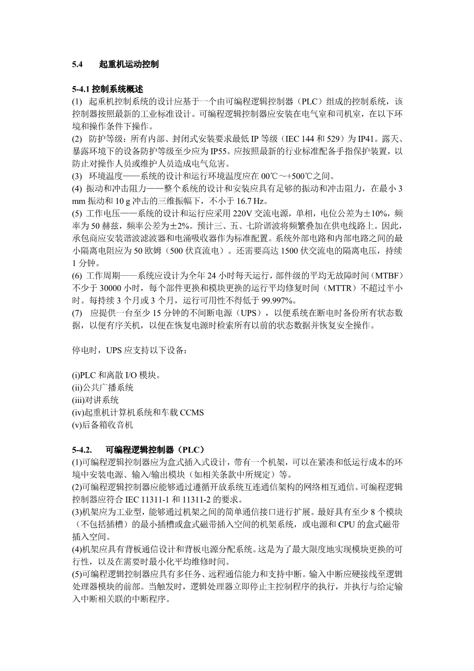
The Crane control system design shall be based on a control system consists of Programmable Logical Controllers (PLC) designed to the latest industrial standards. The Programmable Logical Controllers are to be installed in the electric house and operators cab which are operated in following environment and operating conditions.
(1) Environment - The entire system shall be designed and operated in hot and humid atmosphere where installations are subject to prevailing heavy condensation and high fungi. Equipment shall also be treated so as to resist attacks and entry of bugs and mites such as termites, beetles, fly, etc. All components shall be tropicalize-treated.
(2) Degree of Protection ‑ a minimum IP class (IEC 144 and 529) of IP41 is required for all in house, enclosed installations. Equipment of installations at open, exposed atmosphere shall have an IP class of IP55 as a minimum degree of protection. Finger protection against electrical hazard to operators or maintenance personnel shall be equipped according to the latest industrial standards.
- Ambient Temperature ‑ the system shall be designed and operated in an ambient temperature between 00C to 500C.
- Vibration and Shock Resistance ‑ The entire system shall be designed and installed with an adequate vibration and shock resistance of not less than 16.7 Hz at a 3 dimensional amplitude of minimum 3mm in vibration and 10G in shocks.
- Operating Voltage ‑ the system shall be designed and operated with a power supply of 220VAC, single phase with an electrical potential tolerance of plusmn;10% and a frequency of 50Hz with a frequency tolerance of plusmn;2%. It is expected that harmonics of 3rd, 5th and 7th order will be superimposed on the supply line frequently. Therefore, the Contractor shall install harmonic filters and power surge absorbers as a standard feature. The system shall have a minimum isolation resistance between external circuits and internal circuits of 50M ohm at 500VDC. An isolation voltage of up to 1500VAC for 1 minute is also required.
- Duty Cycle ‑ The system shall be designed to be operated 24 hours a day for the whole year round with a mean time between failure (MTBF) at the component level of not less than 30,000 hours and an operational mean time to repair (MTTR) of not more than frac12; hour per component replacement and module replacement. The operating availability shall be not less than 99.997% per every continuous duration or period of 3 months.
- One unit of Uninterrupted Power Supply (UPS) with a minimum of 15 minutes shall be provided to enable the system to back up all status data for an orderly shutdown in case of power failure so that all previous status data can be retrieved and safe operation can be resumed when the power is restored.
The UPS shall support the following equipment during power failure:
(i)PLC and discrete I/O modules.
(ii)Public address system
(iii)Intercom system
(iv)Crane computer system and on-board CCMS.
(v)Trunk radio
5-4.2. Programmable Logic Controllers (PLC)
(1)The PLCs shall be of cartridge‑insert type design with a rack that can provide the installation of power suppliers, I/O modules (as specified in the related clauses), etc. in a compact and low operating cost environment.
(2)The PLCs shall be able to intercommunicate with each other through a network following the Open System Interconnection communication architecture. The PLCs shall comply with the requirements of IEC 11311 – 1 and 11311 – 2.
(3)The racks shall be industrial type with a capability of expansion via simple communication interface between and among the racks. It is preferable to have a racking system of a minimum slot or cartridge‑insert space for at least 8 module, which excludes the slots, or cartridge‑insert space for the power supply and CPUs.
(4)The racks shall have a back‑plate communication design and back‑plate power supply distribution system. This is to achieve maximum feasibility in module replacement as well as minimise the mean time to repair when it is required.
(5)The PLCs shall have multi-tasking, remote communication capabilities and supporting interrupts. The input interrupts shall be hard wired to the front of the logic processor module. When triggered, the logical processor immediately halts the execution of the main control program and executes the interrupt routine associated with the given input interrupt.
(6)The PLCs shall have sufficient memory capacity to hold control algorithms for more than one process plus at least 30% redundant memory capacity. The program shall be stored in EEPROM and RAM. Facilities shall be incorporated on the PLCs to enable programming of the EEPROM. There shall be facilities and space provided for adding memories for future developments.
(7)The controller system shall provide real time display of programs, data and status at remote sites. The complete cycle time of crane software inclusive of scanning all I/O modules as well as execution of control modules in one cycle shall not be more than 30 milliseconds.
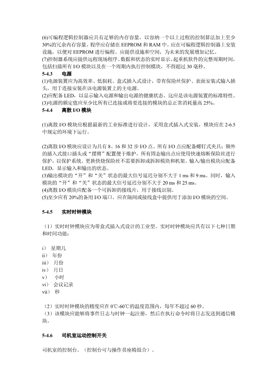
5-4.3 Power Supply
(1)The power supply unit shall be a high efficiency, low loss, cartridge‑insert type design with a fuse protected, surface mount input plug for connecting the main supply mounted to this power supply unit.
(2)LED shall be equipped to show the healthy status of the incoming supply and the outgoing supply. This shall be a standard feature of this power supply unit.
(3)The rating of the power supply shall be at least 25% more than the total normal consumption of all the modules that are connected or that are going to be connected in future.
5-4.4 Discrete I/O Modules
(1)The discr
剩余内容已隐藏,支付完成后下载完整资料


英语译文共 14 页,剩余内容已隐藏,支付完成后下载完整资料
资料编号:[234249],资料为PDF文档或Word文档,PDF文档可免费转换为Word


