某高层办公楼给水排水工程设计毕业论文
2020-05-26 20:25:48
摘 要
Abstract VII
设计说明书 1
第一章 给水系统 1
1.1给水系统方案的选择 1
1.2给水系统组成 2
1.3给水管道的布置与敷设 2
第二章 消防系统 4
2.1室内消火栓系统 4
2.1.1消火栓系统组成 4
2.1.2设备 4
2.1.3室内消火栓的安装与布置 4
2.2自动喷淋系统 5
2.2.1系统组成 5
2.2.2设备 5
2.2.3喷头的选择与布置 5
2.2.4喷淋系统的安装 6
第三章 室内排水系统 6
3.1排水系统的分类 7
3.2室内排水系统选择 7
3.3 排水系统的组成 7
3.4主要设备 7
3.5排水管道安装要求 7
第四章 雨水系统 9
4.1雨水排水系统的选择 9
4.2雨水排水系统的组成 9
4.3雨水管道的敷设与布置 9
设计计算书 10
第一章 给水系统计算 10
1.1用水定额及用水量 10
1.2给水方式 11
1.3设计秒流量的确定 11
1.3.1设计依据 11
1.4生活给水系统水力计算 12
1.4.1 卫生间给水系统水力计算 12
1.4.2低区给水系统水力计算 20
1.4.3中区给水系统水力计算 22
1.4.4高区给水系统水力计算 24
1.5水表的选择 26
1.6管道压力校核 27
1.7供水设备选型 28
1.7.1高区增压设备 28
1.7.2中区区增压设备 29
1.7.3减压阀的设置 30
第二章 室内消火栓给水系统的计算 32
2.1消防水池 32
2.1.1消防水池的设置 32
2.1.2体积计算 32
2.2屋顶消防水箱 33
2.3消火栓保护半径和间距 34
2.4消火栓的确定 35
2.5消火栓的水力计算 35
2.5.1消火栓口所需的水压 35
2.5.2水力计算 36
第三章 自动喷水灭火系统 43
3.1自动喷淋灭火系统的基本数据 43
3.2管道与报警阀布置 43
3.3喷头的选用与布置 43
3.4系统的设计流量 43
3.5水力计算(特性系数法) 44
3.5.1高区喷淋水力计算 45
3.5.2中区喷淋水力计算 47
3.5.3低区喷淋水力计算 50
3.5.4机械车库喷淋水力计算 54
3.5.5 系统水力计算 58
3. 6增压及贮水设备 59
3.6.1 选泵 59
3.6.2消防水箱及稳压设备 59
3.7水泵接合器 59
3.8喷淋减压孔板计算 59
3.8.1机械车库喷淋减压孔板计算 62
第四章 室内排水系统 64
4.1排水体制及排水方式 64
4.2排水系统水力计算 64
4.2.1排水横支管水力计算 64
4.3立管计算 70
4.3.1三层至十层排水立管计算 71
4.3.2二层和夹层单排水立管计算 72
4.4排出管计算 74
4.5集水坑及提升泵计算与选型 74
4.5.1地下室车库集水坑及提升泵计算选型 74
4.5.2消防电梯集水坑及提升泵计算选型 75
4.5.3水泵房集水坑及提升泵计算选型 75
4.5.4汽车坡道集水坑及提升泵计算选型 76
第五章 雨水系统 77
5.1屋面雨水排水方式 77
5.2降雨强度 77
5.3汇水面积 77
5.4设计秒流量 77
5.4.1各立管的汇水面积 77
5.4.2各立管的雨水设计秒流量 78
5.5雨水斗选用 79
5.6连接管选用 80
5.7溢流口排水量 80
5.8立管选用 81
5.9排出管计算 81
参考文献 82
结语 83
致谢 84
摘要
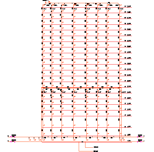
本次的设计是南京市测绘院办公楼给排水工程的设计,该建筑分为地下一层,地上二十三层,总高度为82m,属于高层建筑。给水系统采用分区供水,分为三个区,低区为第一层至第四层,由市政管网直供;中区为第五至第十四层,由变频无负压设备供水;高区为第十五层至二十二层,由变频无负压设备供水。
查规范知道本建筑为一类建筑,防火等级为一级,室内消火栓设计流量为 ,火灾延续时间按3h计,充实水柱高度为13m,水带长度25m,消防立管管径为DN100。自动喷淋系统根据一个报警阀最多控制800个喷头分为三个区,机械立体停车库单独用一个报警阀组。所有报警阀都安装在地下泵房内,各层设有水流指示器、信号阀及末端试水装置。屋顶设有体积为18
 的消防水箱,可以贮存10min自动喷淋灭火系统和室内消火栓系统的用水量,火灾初期由水箱供水,后期由地下室的消防水泵和喷淋泵供水。
本建筑排水系统采用合流排水体制,污水可直接排入城市排水管网集中送至污水处理厂。三至二十二层的排水立管采用专用通气立管,二层和夹层单独排水,地下室的水汇集到集水坑,再由潜污泵提升排出。雨水系统采用内排方式,屋面雨水斗收集屋面雨水后经雨水立管排至雨水井。
关键词:给水系统、自动喷淋系统、排水系统、雨水系统
Abstract
This design is the design of Nanjing surveying and Mapping Institute office building to the drainage works, the building is divided into the ground floor, the ground floor twenty-three, the total height of 82m, belong to the high-rise building.The water supply system is divided into three zones, and the low area is the first layer to the fourth layer, which is directly supplied by the municipal pipe network;The central area is fifth to fourteenth layers, and the water supply of the non negative pressure equipment is frequency conversion;The area is fifteenth to twenty-two layers, the frequency non negative pressure equipment in water supply.
According to the specification, it can be known that this building belongs to class A; its fire rating is grade 1; the design flow of indoor fire hydrant is counting 3h of fire life,Enrich the water column height of 13m, with the length of 25m,fire stand pipe diameter is DN100. Based on the principle that one alarm valve shall control 800 sprayers at most, the automatic spraying system is divided into three regions, among which the mechanical parking system applies one alarm valve separately. All the alarm valves are installed in underground pump house where each floor sets current indicator, signal valve and end water-testing device. The firewater tank in volume of 18 is set at roof, which can store the water consumption of 10min automatic sprinkler system and indoor hydrant system; the water tanks supplies water at the initial stage of fire while the underground fire pump and spray pump supply water in later period.
相关图片展示:
