波形钢腹板PC组合箱形刚构梁桥设计-主跨80m毕业论文
2020-04-18 20:47:26

2019届毕业设计(论文)
课题名称 | 波形钢腹板PC组合箱形刚构梁桥 |
设计-主跨80m | |
院 (系) | 土木工程学院 |
专 业 | 土木工程 |
姓 名 | 冯佳琪 |
学 号 | 1801150201 |
起讫日期 | 2019.2.25-2019.5.31 |
指导教师 | 张健东 教授 |
赖韬 讲师 | |
2019 年 6 月
波形钢腹板PC组合箱形刚构梁桥设计

Design of PC Composite Box Girder Bridge with Corrugated Steel Webs
The project supported by this project is the sub-bridge of Yunbao Yellow River Bridge. This design adopts a three-span continuous rigid frame bridge with 52m 80m 52m. The upper structure adopts corrugated steel web prestressed concrete composite box-shaped rigid frame bridge (main span 80m), the thickness of the box girder and the main beam The height is changed by the parabola of 1.8 times, and the construction method adopts the cantilever construction method. The lower structure adopts double-limb thin-walled bridge piers, the pier body is connected to the frame type abutment, and the foundation adopts the bored pile foundation, and the construction method of the overall cast-in-place construction of the bracket is adopted. According to the calculation task book design, the design parameters and environmental impacts are fully considered to bridge the layout, and two layout schemes are designed.
Compare and select the bridge type, determine the appropriate preliminary design plan, further consider the optimized structural arrangement and section size, and then calculate the bridge dead load, live load and secondary internal force based on midas software modeling, and calculate the load combination on this basis. And draw the beam bridge bending moment and shear envelope diagram; secondly, calculate the minimum number of prestressed bars required for the bridge according to the internal force value under the large cantilever state, and estimate the number of prestressed tendons again according to the short-term effect combination in the bridged state. The external prestressing tendons are laid and the prestress loss is calculated; then the structural reinforcement is considered reasonably; finally, the pier and pile foundation are designed separately, and it is checked whether the continuous rigid frame bridge meets the design requirements. After comprehensive analysis and calculation, the design meets the requirements of relevant specifications and has certain application value.
Key Words: design; continuous rigid frame bridge; cantilever construction; prestress
第一章 方案设计
1.1 跨径布置
 52m 80m 52m=184m
本联为三跨连续刚构梁,由参考文献[1](P65)可知,三跨连续刚构梁合理的跨径布置为:边跨与中跨之比为0.5~0.8,且悬臂施工边中跨之比小于等于0.65。该桥选择的边跨与中跨之比为0.65。


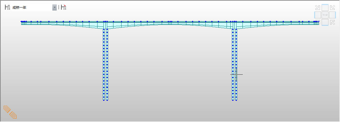
图1-2 计算跨径布置图
由上图可知连续梁两端分别有0.56m 和 0.56m 的悬臂段,但由于其长度很小,并且位于支座顶部,对内力影响很小,故在内力计算中忽略不计。故计算跨径为:
51.4m 80m 51.4m
1.2 顺桥向设计
1.2.1纵坡设计.
为了满足桥梁纵向排水的需要,根据设计任务书要求,本设计桥梁纵坡取为2.0%。但由于纵坡坡度很小,对桥梁跨径和梁高基本没有影响,故在具体计算中,计算模型按平坡设计。
1.2.2梁高设计
以上是毕业论文大纲或资料介绍,该课题完整毕业论文、开题报告、任务书、程序设计、图纸设计等资料请添加微信获取,微信号:bysjorg。
相关图片展示:


